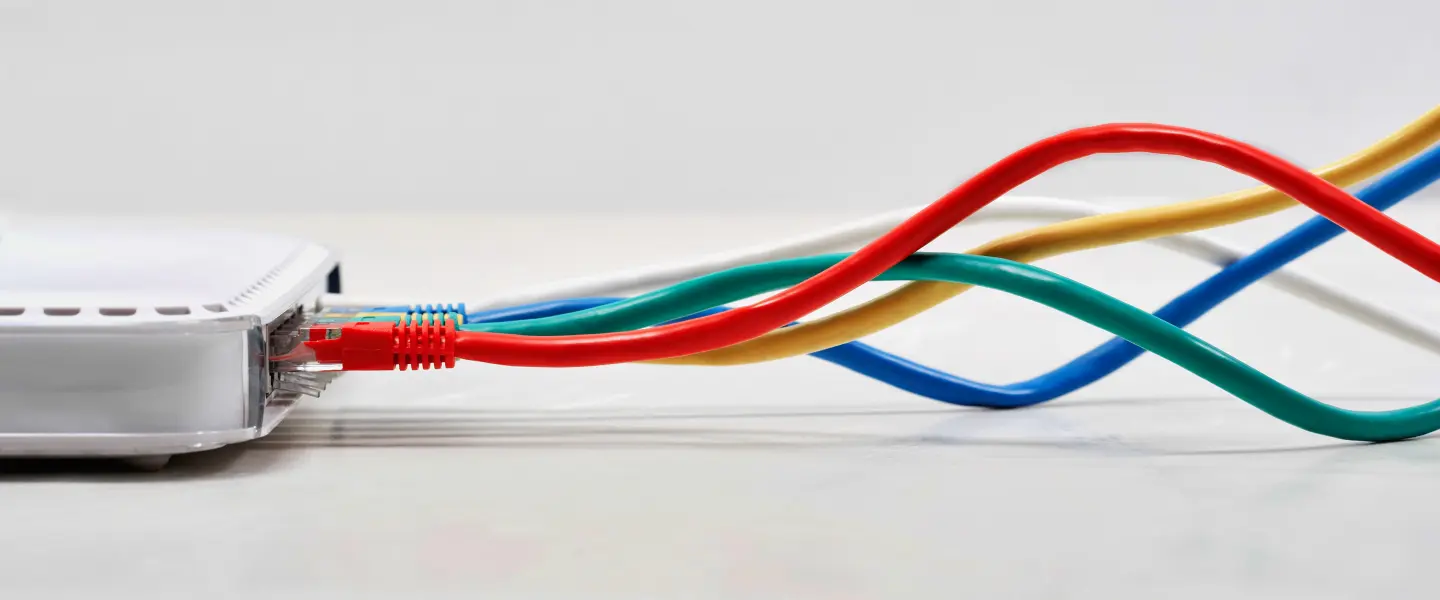
1. Overview
Under IEEE 802.3af and 802.3at protocols, power-supplying devices provide direct current to powered devices. This transmission is conducted over standard Category 5 or Category 6 twisted-pair cables. Ethernet cables consist of four twisted-pair wires. Power delivery logic is split into Mode A and Mode B based on the physical wire sequence.
2. Mode Definitions and Physical Topology
(1) Mode A (End-to-End Mode)
Mode A uses “phantom power” technology to deliver DC power over the wire pairs used for data transmission.
Physical Wiring Sequence: Power is transmitted via wire pairs 1-2 and 3-6.
Signal Multiplexing: DC power and Ethernet differential signals coexist on the same wire pair. At the transmitter end, current is injected via a transformer center tap. At the receiver end, current and data are separated using the same balun circuit.
Typical Applications: Primarily used in scenarios where PDs are directly connected to PoE switches.
(2) Mode B (Mid-span Mode)
Mode B utilizes “idle” wire pairs in 100Mbps Ethernet to deliver power. Achieving physical separation of the power and data channels.
Physical Wiring Sequence: Power is transmitted over the 4-5 and 7-8 wire pairs.
Signal Isolation: In 10/100M networks, data uses only pairs 12 and 36. So pairs 45 and 78 serve exclusively as power transmission carriers. In Gigabit networks, since all 8 pairs carry data. Mode B similarly employs phantom power technology similar to Mode A.
Typical Applications: Commonly used with PoE injectors or non-PoE switches to extend power over Ethernet.
3. Comparison of Core Differentiating Technical Specifications
|
Technical Specifications
|
Mode A (Alternative A)
|
Mode B (Alternative B)
|
|
Power Delivery Interface
|
Data Pairs
|
Spare Pairs
|
|
Pin Configuration
|
1, 2 (+) & 3, 6 (-)
|
4, 5 (+) & 7, 8 (-)
|
|
Physical Design
|
Endpoint
|
Midspan
|
|
Compatibility
|
Full support for 2-pair and 4-pair cables
|
Ensure that all 8 wires in the cable are connected
|
|
Gigabit Support
|
Multiplexing via center tap
|
Multiplexing via the center tap
|
4. Key Original Manufacturer Technical Logic
(1) Polarity-Insensitive Design
According to IEEE standards, all Powered Devices (PDs) must integrate a bridge rectifier internally. This means that PDs must be compatible with both Mode A and Mode B. Regardless of the mode used by the Power Sourcing Equipment. The PD can automatically perform polarity correction and route the current to the internal DC/DC conversion module.
(2) Negotiation and Handshake Protocol
Before formally outputting 48V current, the PSE must undergo two stages: detection and classification.
Detection Stage: The PSE outputs a voltage of 2.7V–10.1V to detect whether the PD has a 25kΩ characteristic resistance.
Classification Stage: The PSE measures the PD’s current consumption to confirm its power rating.
Note: The selection of the power supply mode is typically determined by the hardware design on the PSE side. Once the hardware circuit is closed, the power supply path is fixed.
5. Manufacturer Engineering Recommendations
Cable Selection: The use of four-core cables masquerading as eight-core cables is strictly prohibited. If Mode B power supply is used, substandard cables will prevent the power circuit from closing. Causing the device to repeatedly reboot or fail to power on.
Long-Distance Transmission: Since Mode B power delivery utilizes the 4, 5, and 78 wire pairs. During long-distance transmission, resistance causes a slight voltage drop and power loss. This physical outcome differs slightly from the performance of Mode A.
For transmission distances exceeding 80 meters, prioritize using pure copper standard Category 6 cable. This ensures optimal performance for long-range power delivery.
Mode Compatibility Troubleshooting: During on-site testing, ensure the PSE signal and the PD’s detection front end are properly isolated. There must be no physical short circuit between these two points.

